Senior Year
Senior Design

The Problem:
For those recovering from or at risk of cancer, heart or other diseases, a stent can be the difference between life and death. Stents can be expanded into a blocked passage to resume normal blood, air, or other flow. Aerotech is a company that supplies stent manufacturers with the machines they need to manufacture the stents. Currently, during the laser ablation process, the stent is manually loaded and unloaded from the mandrel. This is a time-consuming process that can introduce errors in manufacturing. Aerotech would prefer to supply an all-in-one solution that does not require a human operator.
The Solution:
Our team developed an automated work cell designed to handle one size of stent. The central piece of the work cell consisted of a hobby grade robotic arm. The arm we selected was the Lynxmotion LSS 4 DoF arm. The primary design aspects of the project included developing the infeed, outfeed, and gripper as well as the code required to control the arm.
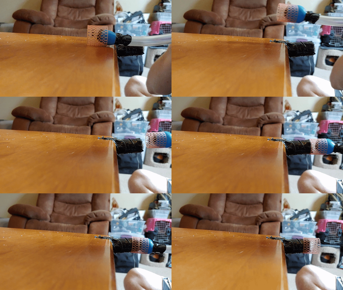
Four gripper prototypes were developed and tested. They were an inflatable gripper, a three-wire gripper, a three-prong gripper, and a compliant gripper. We decided to ultimately go with the compliant gripper for its simplicity.


An infeed mechanism was developed that could feed one stent at a time to the arm from the same location. A 3D printable version of the current mandrel in use was designed and printed. An outfeed mechanism was also designed so the stents could be dropped into a bin. A video of the entire process is shown below.
A contact sensor was also developed to catch errors by determining if the stent was properly gripped. This sensor proved to not be reliable enough for production needs, but it serves as a launching point for further improvement.
My Contribution:
As the resource manager, I oversaw all purchases for the project. Because of my previous experience with 3D printing, I was also in charge of 3D printing the parts and assembling them into the final work cell. I was also involved with creating the code used to run the arm and I worked on the bending analysis we performed on the gripper. The three wire gripper shown in the first gif above was my design. This gripper was our second choice, but it was not pursued due to its complexity.
Carnegie Robotics Internship

I spent twelve weeks over the summer working as an intern for Carnegie Robotics. During my short twelve weeks, I worked on a wide variety of projects. I researched RTV silicones and flexible epoxies and developed a stress test to evaluate them. I also tested the impact of bandpass filters on stereo cameras. During that process I discovered a way to make the cameras perform up to 8 times better by adjusting the lens polarization. I also designed multiple jigs and fixtures for camera calibration and vibration testing. My last project was to design and have manufactured a lid that housed electronics and blower fans. This was incorporated into an agricultural robot. This was my first weldment and was made in house. It is still in use and can be seen here.
The most important thing I took away from this experience was learning how to work remotely. Fortunately, my internship was not cancelled because of COVID-19, but it did mean that I had to integrate into a company without meeting face to face. Our regular morning meetings with our small group of engineers were invaluable. Having a solid tech support team was also helpful when setting up VPNs and accessing network drives. While it was not always easy, I am now confident that I can be effective when working remotely.
Automatic Solar Sextant
The Problem:
For our final measurements 2 project, we had to choose something to measure. My team decided to attempt to measure our location on the Earth without the aid of GPS.
The Solution:

The approach we took to this problem was to measure the inclination of the sun at solar noon (when the sun reaches its peak height). By knowing this inclination, what hemisphere you are in, and the time of year to compensate for the tilt of the Earth, you can calculate your latitude. To find your longitude you simply have to know at what time solar noon occurred in G.M.T. To measure the inclination, we used four light sensors separated by two intersecting perpendicular walls. These walls would cast a shadow on the light sensors if the device was not pointing directly at the sun. The device was articulated by two servos and should have been able to track the sun through the sky. An IMU mounted on the device would have measured the inclination. A real time clock was used to keep track of G.M.T. All of this was purchased with a limited budget of $100. Unfortunately, due to COVID-19, this project was never completed. We did perform calculations and determined that our expected accuracy was +-42 miles in latitude and +- 10 miles in longitude. The video below shows our final presentation on the project.
My Contribution:
For this project, I did the majority of the sensor selection and compatibility checks. Unfortunately, we never got to test our idea and it is a project I may revisit in the future.